V. Making it more interesting
[Previous section]
[Next section]
[Back to the index]
In this section we are going to define a topology with four nodes in which
one node acts as router that forwards the data that two nodes are sending to
the fourth node. I will explain find a way to distinguish the data flows
from the two nodes from each other, and I will show how a queue can be monitored
to see how full it is, and how many packets are being discarded.
V.1. The topology
As always, the first step is to define the topology. You should create a
file 'example2.tcl', using the code
from section
IV.1 as a template. As I said before, this code will always be similar. You
will always have to create a simulator object, you will always have to start
the simulation with the same command, and if you want to run nam automatically,
you will always have to open a trace file, initialize it, and define a procedure
which closes it and starts nam.
Now insert the following lines into the code to create four nodes.
set n0 [$ns node]
set n1 [$ns node]
set n2 [$ns node]
set n3 [$ns node]
|
The following piece of Tcl code creates three duplex links between the nodes.
$ns duplex-link $n0 $n2 1Mb 10ms DropTail
$ns duplex-link $n1 $n2 1Mb 10ms DropTail
$ns duplex-link $n3 $n2 1Mb 10ms DropTail
|
You can save and start the script now. You might notice that the topology
looks a bit awkward in nam. You can hit the 're-layout' button to make it
look better, but it would be nice to have some more control over the layout.
Add the next three lines to your Tcl script and start it again.
$ns duplex-link-op $n0 $n2 orient right-down
$ns duplex-link-op $n1 $n2 orient right-up
$ns duplex-link-op $n2 $n3 orient right
|
You will probably understand what this code does when you look at the topology
in the nam window now. It should look like the picture below.
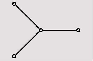
Note that the autolayout related parts of nam are gone,
since now you have taken the layout into your own hands. The options for the
orientation of a link are right, left, up, down and combinations of these
orientations. You can experiment with these settings later, but for now
please leave the topology the way it is.
V.2. The events
Now we create two UDP agents with CBR traffic sources and attach them to the
nodes n0 and n1. Then we create a Null agent and attach it to node n3.
#Create a UDP agent and attach it to node n0
set udp0 [new Agent/UDP]
$ns attach-agent $n0 $udp0

# Create a CBR traffic source and attach it to udp0
set cbr0 [new Application/Traffic/CBR]
$cbr0 set packetSize_ 500
$cbr0 set interval_ 0.005
$cbr0 attach-agent $udp0

#Create a UDP agent and attach it to node n1
set udp1 [new Agent/UDP]
$ns attach-agent $n1 $udp1

# Create a CBR traffic source and attach it to udp1
set cbr1 [new Application/Traffic/CBR]
$cbr1 set packetSize_ 500
$cbr1 set interval_ 0.005
$cbr1 attach-agent $udp1

set null0 [new Agent/Null]
$ns attach-agent $n3 $null0
|
The two CBR agents have to be connected to the Null agent.
$ns connect $udp0 $null0
$ns connect $udp1 $null0
|
We want the first CBR agent to start sending at 0.5 seconds and
to stop at 4.5 seconds while the second CBR agent starts at 1.0
seconds and stops at 4.0 seconds.
$ns at 0.5 "$cbr0 start"
$ns at 1.0 "$cbr1 start"
$ns at 4.0 "$cbr1 stop"
$ns at 4.5 "$cbr0 stop"
|
When you start the script now with 'ns example2.tcl', you will
notice that there is more traffic on the links from n0 to n2 and
n1 to n2 than the link from n2 to n3 can carry. A simple calculation
confirms this: We are sending 200 packets per second on each of the
first two links and the packet size is 500 bytes. This results
in a bandwidth of 0.8 megabits per second for the links from n0 to n2
and from n1 to n2. That's a total bandwidth of 1.6Mb/s, but the
link between n2 and n3 only has a capacity of 1Mb/s, so obviously
some packets are being discarded. But which ones? Both flows are
black, so the only way to find out what is happening to the packets
is to monitor them in nam by clicking on them. In the next two
sections I'm going to show you how to distinguish between different
flows and how to see what is actually going on in the queue
at the link from n2 to n3.
V.3. Marking flows
Add the following two lines to your CBR agent definitions.
$udp0 set class_ 1
$udp1 set class_ 2
|
The parameter 'fid_' stands for 'flow id'.
Now add the following piece of code to your Tcl script,
preferably at the beginning after the simulator object has
been created, since this is a part of the simulator setup.
$ns color 1 Blue
$ns color 2 Red
|
This code allows you to set different colors for each flow id.
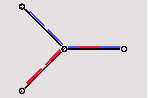
Now you can start the script again and one flow should be blue,
while the other one is red. Watch the link from node n2 to n3 for
a while, and you will notice that after some time the distribution
between blue and red packets isn't too fair anymore (at least
that's the way it is on my system). In the next section I'll
show you how you can look inside this link's queue to find out
what is going on there.
V.4. Monitoring a queue
You only have to add the following line to your code to monitor the
queue for the link from n2 to n3.
$ns duplex-link-op $n2 $n3 queuePos 0.5
|
Start ns again and you will see a picture similar to the one below after
a few moments.
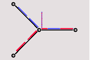
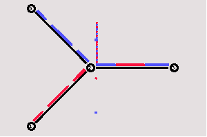
You can see the packets in the queue now, and after a while you can even see
how the packets are being dropped, though (at least on my system, I guess
it might be different in later or earlier releases) only blue packets are
being dropped. But you can't really expect too much 'fairness' from a simple
DropTail queue. So let's try to improve the queueing by using a SFQ (stochastic
fair queueing) queue for the link from n2 to n3. Change the link definition
for the link between n2 and n3 to the following line.
$ns duplex-link $n3 $n2 1Mb 10ms SFQ
|
The queueing should be 'fair' now. The same amount of blue and red packets
should be dropped.
You can download the full example here.
[Previous section]
[Next section]
[Back to the index]
ns-users
[email protected]