
The X-Bone dynamically deploys and manages Internet overlays to reduce configuration effort and increase network component sharing. The X-Bone discovers, configures, and monitors network resources to create overlays over existing IP networks. Overlays are useful for deploying overlapping virtual networks on shared infrastructure and for simplifying topology.
The X-Bone extends current overlay management by adding dynamic resource discovery, deployment, and monitoring, and allows network components (hosts, routers) to participate simultaneously in multiple overlays.
The X-Bone’s two-layer IP in IP tunneled overlays support existing applications and unmodified routing, multicast, and DNS services in unmodified host operating systems. This two-layer scheme uniquely supports node revisitation and recursive overlays, which is critical for fault tolerance and dynamic relocation.
The X-Bone uses multicast to simplify resource discovery, and provides secure deployment as well as secure overlays.
Software
Architecture
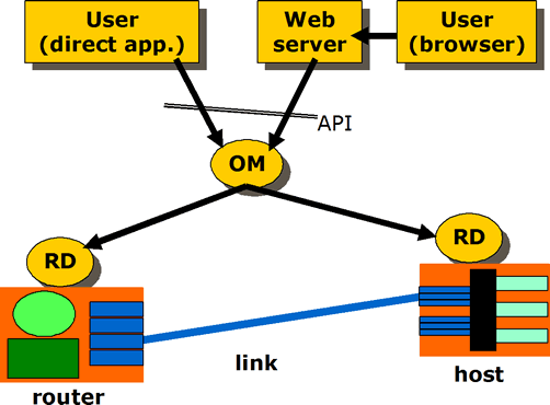
The X-Bone is a system for the automated deployment, management, coodination, and monitoring of IP overlay networks. Its core is composed of Overlay Managers (OM) which deploy and coordinate the overlay itself, and Resource Daemons (RD), which coordinate the resources of individual network components. It also includes support for a graphical user interface (GUI) and a more direct API (shown in the figure below)
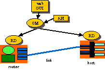
The GUI/API requests the overlay, and monitors its progress. The OM advertizes an invitation to create a new overlay, then configures the components, and monitors the result. The Resource Daemon coordinates resource use on the individual components, and translates generic configuration into machine-specific form.
TCP/SSL is used for secure configuration to take advantage of TCP’s reliable channel, and reduce the number of different security schemes required in X-Bone [14]. X-Bone uses a web-based GUI for user request of an overlay deployment. Web browsers already support SSL, so the user’s request is secure on the path to the OM. For simplicity, we use the same mechanism between the OMs and RDs. Alternate schemes, such as PGP, would require multiple mechanisms within the OM, and different protocols between different pairs of components.
This architecture utilizes a single, well-known multicast channel for invitation announcements, and separate reliable channels for configuration and monitoring. It is based on the multicast announcements in M-Bone teleconferencing; in fact, X-Bone effects an overlay as if it were a teleconference among its OM and the RDs of its router and host components.
Overlay Managers
Overlay managers (OMs) deploy overlays. A user creates an overlay deployment by sending a high-level request to an OM, either via a web-based GUI or by running a program that emits the request to the OM’s API. Each overlay is coordinated by a single OM; large overlays are created by divide-and-conquer, where a single OM forks sub-overlay requests to other OMs. Fault tolerance is achieved by replicating overlay coordination state in multiple backup OMs.
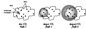
Figure 1. Resource discovery using increasing-TTL multicast invitations
An OM creates an overlay in phases, using multicast to discover available resources and TCP/SSL to configure and monitor those resources [14]. The overlay request is translated to an invitation, and the invitation is multicast using UDP. An invitation indicates the user requesting the overlay and a set of simple conditions, such as a specific operating system, bandwidth requirements, etc. Invitations currently fit in a single UDP packet; where larger messages are required, multiple copies of each component packet can be emitted and cached for reassembly. Invitations are repeated with increasing TTLs until a sufficient number of invitees respond, or until a preset search limit is exceeded: i.e., an expanding ring search [17].
Resource Daemons
Resource daemons (RDs) are daemons that configure and monitor the resources of routers and hosts. The RDs listen for multicast invitations, and respond when their available resources and permissions match the incoming request. Responses are in the form of TCP/SSL (X.509 encrypted) connections back to the source OM, where each RD indicates its particular capabilities. The OM selects from among the responding RDs, and picks an appropriate subset. Once the set of RDs is selected, the OM determines configuration information, such as tunnel endpoint addresses, routing table entries, etc., and sends specific configuration information to each RD. Once an overlay is thus deployed, the TCP/SSL connections are released and the overlay is up. Subsequent overlay actions are initiated by the OM, such as keep-alive pings, liveness and status requests, and modifying or dismantling configurations.

Figure 2. Responding to invites, selecting, and configuring the overlay.
The OM emits heartbeat pings to refresh the state of the RD components. When a RD no longer hears from an OM, all overlays of that OM are released from the RD state. Both RD and OM state
are kept on disk, and reloaded after reboots or restarts.
X-Bone Protocols
X-Bone API
The XBone API protocol allows a user process or graphical interface to request the deployment of an IP overlay, and to monitor that overlay once deployed. It is used for messages between the user interface or an external program and an Overlay Manager.
Initially, the API requests that an overlay be created, and is returned the result of that action. Subsequent request/response explicitly monitor the depoyed overlay. Alarm messages act as alarms from the overlay to the user side of the API, to indicate an urgent change of status.
This protocol typically uses unicast UDP and TCP, though there are plans for multicast UDP for monitoring.
X-Bone Control
The X-Bone Control protocol is used for exchanges between the Overlay Manager and the Resource Daemons. This protocol operates in several phases:
| Invitation | The OM multicasts UDP invitations with increasing TTLs, searching for sufficient RDs with available resources and who are capable of participating in the advertised invitation. |
| Configuration | The OM connects via unicast TCP to the RDs, and sends configuration messages. The OM sends request/response messages over this channel, until either the entire overlay is deployed or some part fails; in the latter case, it tears down the configuration before closing the connections. |
| Monitoring | Various unicast UDP and TCP and multicast UDP messages are used to monitor the deployed overlay, including:
Echo-algorithm-style pings to detect the presence of the deployed tunnels Refresh messages for the OM to maintain the soft state at the RDs. In the absence of these messages, RDs tear down overlay state after a timeout. Alarms for RDs to trigger corrective action by the OM |
Uses
This is the primary configuration for the X-Bone. In particular, to do a network experiment, each site must be configured with the following information:
1. Each RD must list all participating OMs as allowed
2. Each RD must list all usernames (from X.509 user certificates) that are allowed
3. Each host or router where users rely on DNS resolution must include the list of DNS servers for the overlays deployed. If the DNS names used are global (e.g., registered in the current DNS hierarchy), no additional configuration is required. However, if the DNS names are local (e.g., you’ve decided to deploy a local DNS, in a sense), that DNS must be appropriately configured.
How are the hosts and routers named?
Both hosts and routers retain their original base name (goo.isi.edu’s would be ‘goo’), and acquire the suffix of the overlay name followed by the X-Bone shared suffix. If your X-Bone is configured as “xbone.univ.edu’, and you’ve deployed an overlay called ‘boom’, then that host would be known as “goo.boom.xbone.univ.edu’.
The X-Bone provides tools to make selecting an overlay and referring to hosts and routers in an overlay easier. In particular, xb-pick allows you to set the default DNS suffix in a window or for a process. In the above example, you’d set xb-pick to select the ‘boom’ overlay, and it would set the process’s suffix to ‘boom.xbone.univ.edu’. Then, inside that window, ‘goo’ would refer to goo.boom.xbone.univ.edu, as expected.
How do I “keep the streams from crossing” (isolate experiments)?
That depends on what you want to experiment with. The X-Bone already keeps IP traffic on different overlays separated. However, there are cases where more strict separation is required. There are three basic options:
-
If you want SECURITY
Use IPSEC’d overlays. IPSEC prevents outside traffic from being accepted (spoofed source) into an overlay, and prevents intermediate hops on a tunnel from accessing the data inside packets.
-
If you want to do PERFORMANCE EXPERIMENTS
Set each component (router and host) to participate in ONE overlay at a time (in /etc/xbone/Xbone_daemon.conf set the variable MaxOverlayCount of the XboneNode to 1). Put all components on a switch that has ‘full switching capacity’ (i.e., can handle full bandwidth between any two nodes at a time). Make sure this is a switch, not a bridge. If you plan to do multicast experiments, make sure the switch ‘speaks’ IGMP.
-
If you want to do CONCURRENT TESTS OF DIFFERENT CONFIGURATIONS
Currently, the X-Bone understands only configurations that have been ‘wired’ into the code, indicating the operating system (FreeBSD, Linux, Solaris) and the security patches (KAME, NIST). However, it can be useful to be able to select a subset of machines based on some other property, such as “has a new TTCP protocol” or “speaks RSVPv2”. In those cases, another way to indicate which machines are required is needed.
The best way to emulate configurations created by users is via configuration of the ACL. Create additional X.509 certificates whose ‘user’ name matches the configuration needed, and configure the ACLs in /etc/xbone/Xbone_daemon.conf to allow access only to users whose certificates match. E.g., each user asks for a certificate with a set of suffixes. e.g., ‘-TTCP’, ‘-RSVPv2’, etc. User ‘joe’ would have certificates:
1. joe-TTCP
2. joe-RSVPv2
When user ‘joe’ wants to do a TTCP experiment, he uses his joe-TTCP certificate. Only nodes configured to allow joe-TTCP would respond to invitations.
-
If you want to have MULTIPLE GROUPS OF STUDENTS doing experiments
This too is solved with ACLs. Each group of students deploys RDs with ACLs that allow only their group members. A SINGLE OM suffices.
(Read more on access control lists.)
Teaching networking lab classes
The X-Bone can also be used for teaching networking classes, especially for networking labs.
-
How do I keep the student experiments separate?
See above, under “keeping the streams from crossing”.
-
Where can I get help if needed?
Contact the X-Bone group directly. We are particularly interested in having it used for lab classes, and would be glad to see how we can help you.
VPN deployment
Basically, deploy an overlay with IPSEC and use your applications as usual, using the overlay names of the endpoints.
FAQ
![]()
(The Official X-Bone cookie – A.S. Hughes)
About X-Bone
The X-Bone is a software system that configures overlay networks, also known as VPNs. It uses a web-based GUI, as well as Perl-based daemons, to discover, configure, and deploy an overlay network. The X-Bone installs routes, configures interfaces, updates DNS entries, and installs IPSEC keys.
What is the X-Bone useful for?
The X-Bone can be used for:
- Deploying VPNs
- Network research
- Network lab classes
How is the X-Bone different fron other VPN and overlay systems?
The X-Bone differs from other VPN and overlay systems in the following ways:
- Supports multiple concurrent overlays
- Requires no kernel or application modification
- Uses no new network-level protocols (only IP)
- Supports data security (via IPSEC) without requiring application support
- Provides control security (via X.509/SSL)
Can the X-bone deploy more than one overlay at a time?
Yes! The X-Bone can deploy multiple concurrent overlays. A single host or router can participate in more than one overlay at a time as well.
Is the X-Bone secure?
The X-Bone includes a deamon that configures interfaces and installs routes on hosts and routers. Messages between the GUI and the daemon are encrypted using X.509 (via software known as SSL), the same software used to encrypt commercial web purchases.
People
Joe Touch – PI
Greg Finn – staff
Lars Eggert, Amy Hughes, Yu-Shun Wang – students
Past Faculty, Staff and Students
2000 Summer Graduate Research Experience Program
Osama Dosary, Noparut Vanitcha
1999 Summer Graduate Research Experience Program
Oscar Ardaiz, Alper Demir, Deepesh Chouhan, Wei-chun Chao, Tze-Wei Sou
Project Alumni
Anindo Banerjea, Ankur Sheth, Steve Hotz, Stephen Suryaputra, Shitanshu Shah
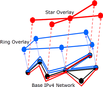
The Need for Multilayer Tunneling
X-Bone uses two-level tunnels. Each IP packet in an overlay is wrapped in two additional IP headers. The innermost (overlay) header is the endpoint in the overlay, i.e., it contains the overlay interface addresses. The next layer acts as a link layer in the overlay, and includes the source and destination addresses of the link interfaces. These link layer addresses are represented by a separate set of IP addresses, also internal to the overlay. The final IP header indicates the source and destination endpoints in the base network. Note that the base network can be another overlay, providing stacked or recursive overlays. The header order is shown in Figure 1.

Figure 1. X-Bone header format: double tunneling results in three layers of headers
The additional tunnels are required to allow multiple tunnels between two components, even within the same overlay. Such doubly-connected components are useful to emulate systems with larger numbers of components, i.e., 50-node rings simulated by using 10 router nodes. The additional layer also permits the use of multicast and dynamic routing algorithms inside the overlay, because such systems effectively operate on the link IP layer. Without that layer, it would be impossible to decouple intra-overlay routing from base-layer routing.
The two layers of the encapsulation change at every overlay hop, as shown in Figure 2. Hosts are indicated by their single overlay interface (A, D) and overlay link addresses (Q, T); the router is indicated by its pair of overlay interface (B and C) and overlay link addresses (R and S). Each component is shown as using a single, canonical base address for base-layer routing (X, Y, and Z); this can be relaxed for multihomed systems. X-Bone requires that routers are multihomed inside the overlay, according to the standard Internet practice
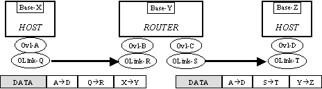
Figure 2. A single packet traverses the overlay – modifying both outer IP headers at each hop
In this figure, an application on overlay host A sends a packet to overlay host D. On the first hop (left), it is first wrapped with an IP header indicating its overlay link endpoint addresses QàR, and then wrapped with the base layer addresses of the endpoints of that tunnel, X and Y. On the second hop (right), both these outer encapsulation headers are removed and replaced with the overlay link and base layer tunnel endpoints of the next hop (S,T and Y, Z). IPSEC authentication or encryption occurs as a modification of the QàR or SàT overlay link headers. The X-Bone uses separate transport-mode IPSEC on these inner headers, i.e., first the IP in IP header is added, then IPSEC is performed to secure the packet Figure 3.
![]()
Figure 3. IPSEC’d X-Bone packet
X-Bone is currently implemented using separate IP address spaces both for the overlay endpoint addresses and the overlay link addresses. The use of separate address spaces effectively encodes the overlay identifier inside the IP addresses, allowing conventional dynamic routing and forwarding at the routers, and conventonal IP demultiplexing at the destination host. This can be relaxed to allow address reuse, provided the decapsulation steps in routers (for forwarding) and end hosts (for demultiplexing) keep sufficient context of the discarded layers of IP headers. Current overlay implementations discard this state, requiring global addresses. Note that overlay addresses can be reused among overlays that do not themselves overlap; this can easily be incorporated in the negotiation process. These issues are covered in more detail in the discussion of IPSEC.
X-Bone’s dual-layer tunnels allow existing dynamic routing and network diagnostic tools to be used inside an overlay, transparent to the base network. This has been used to deploy dynamic routing across non-cooperating administrative domains, where only the hosts involved need participate in the routing algorithms. This has been demonstrated in the X-Bone system, and dynamic routing using RIP (via gated) and multicast (mrouted) are supported inside deployed overlays.
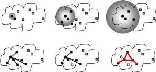
Figure 4. User views of a network mapping utility; different views in different windows
Routing
Manual overlay setup and teardown requires manual configuration of the interfaces and routing tables on all participating machines. Such configuration does not scale well to an overlay that includes a large number of machines or a diverse set of operating systems and routing packages. X-Bone automates the routing process, auto-detecting the routing package and hiding the configuration details from the user.
X-Bone differentiates overlays by assigning a contiguous range of addresses to each overlay. By limiting the routing of overlay addresses, they can be privatized.
Virtual Network Routing and IPsec
The X-Bone supports IPsec in the overlay using transport-mode IPsec, rather than tunnel-mode IPsec, as would be expected in an overlay. The combination of transport mode IPsec and an IPIP link tunnel allows the X-Bone to support dynamic routing over IPsec’ed links, which requires extraordinary coordination of key databases and routing tables if done in conventional (tunnel-mode) IPsec overlays.
Dynamic routing in an overlay network can interfere with the traditional use of IPsec to secure overlay links. IPsec authenticates or encrypts links in an X-Bone overlay. IPsec can interfere with forwarding decisions in overlay routers, however.
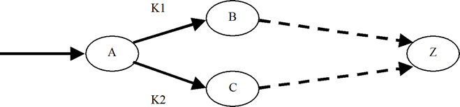
Consider a packet P entering router A, destined ultimately for host Z. There are two possible paths to Z, one through B, the other through C. The B path begins with an overlay link keyed with K1; the C path, with K2. Per-link keys are required for robustness, to avoid needlessly compromising keys.
In an implementation where IPsec processing precedes forwarding decisions, Router A must decide which key to use (K1 or K2) before it has decided which path to take (via B or via C). Some of the forwarding decisions (i.e., routing table) must then be represented in the IPsec rule base, so that packets destined for Z are tagged to use K1. The IPsec rules must reflect the current routing table, imposing configuration and synchronization effort on the routing protocol implementation. Current routing protocols do not support synchronous IPsec rule updates.
IPsec relies on policy databases to determine key usage and requires that keying precedes forwarding. This is not consistent with the use of per-hop keys and dynamic routing protocols. An alternative to binding keys to rules is to bind keys to virtual interfaces, as in the NIST Linux implementation. Keys are bound to links by conventional routing rules, rather than policy-based rules in a separate key database. This allows the key decision to come after forwarding. A forwards via B by using virtual interface V1; everything from V1 is encrypted with K1, then sent to B.
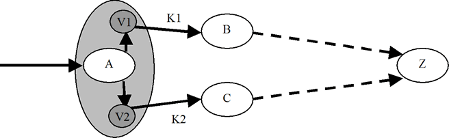
The X-Bone takes advantage of this scheme, even in systems that bind keys to IPsec rule bases. In the X-Bone, tunneling is decoupled from keying, and tunneling is always performed first.
In the example, V1 performs the link-layer encapsulation, and K1 would add the link key. This allows the IPsec rules to remain static, as in “encrypt everything wrapped in this overlay link header.” Dynamic routing algorithms update the routing table, and determine which virtual interface, and, by consequence, which key. The X-Bone is the only known overlay system that integrates both IPsec support and dynamic routing.
This example highlights the issue of lost context: When an encapsulated packet is received, it is unwrapped, and forwarded by the router or demultiplexed to endpoint connections in the host. Forwarding and demultiplexing decisions do not depend on the state of the additional encapsulation headers; this state is discarded as it is removed, so is not available anyway. This means that the interior packet addresses must be globally unique, unless host kernel and router firmware modifications are made to support retaining this state. Uniqueness is per-component. Addresses can be reused on overlays that do not share components, i.e., that participate in both overlays. Routers that provide tunneling only (i.e., intermediate on the tunnel path) do not count as part of an overlay.
Security
The X-Bone changes the configuration of remote machines automatically on behalf of users. This requires strong authentication and encryption mechanisms to prevent abuse. The first part of this document focuses on security issues in the management system.
The X-Bone can also optionally deployed secured overlays. Security issues related to the deployed overlays are discussed in another section of this document.
The following basic assumptions apply to the X-Bone security mechanisms:
- Any required storage is unencrypted with root-only access. The root user has full control over all system parameters used by the X-Bone, and can obtain the information stored through other means.
- Nodes participating in multiple overlays act as crossover points. If an attacker gains root access to a machine that is part of one or more overlays, all overlays are compromised.
Management System Security
There are three principle groups of agents in the X-Bone system: users, resource daemons and overlay managers.
- Users have specifications for an overlay they want deployed and have unsophisticated front-ends that allow expression of specs, but cannot make decisions. (Currently, COTS web browsers are X-Bone front ends.)
- A resource daemon (RD) controls access to configuration of networked resources (routers, hosts, and links), according to an ACL configuration set by resource owner.
- An overlay manager (OM) is an intelligent agents that acts on behalf of users, gathering and coordinating the resources required for an overlay by communicating with resource daemons.
X-Bone security mechanisms use strong cryptography based on X.509 certificates. SSL is used to authenticate and encrypt all TCP-based communication, and S/MIME is used to authenticate and encrypt all unicast UDP communication. Multicast UDP messages are only authenticated, not encrypted. Two-way authentication is enforced; specifically, SSL’s one-way authentication mode is never used.
X.509 has a hierarchical trust model with designated, well-known certification authorities (CAs). A principal considers a peer’s certificate to be valid (thus authenticating the other party) if and only if a signature chain exists that contains a signature by a CA the principal trusts. The X-Bone project acts as a CA for all X-Bone-related keys. Keys certified by other well-known CAs may also be used (configurable).
Communication Overview
During a typical X-Bone transaction, a user will contact an OM, which parses and executes the user’s request. The OM then executes sub-transactions with some RDs, carrying out the user’s request. Eventually, the OM will return some information to the user, finishing the transaction.
Note that users (and front-ends) do not construct the required commands to coordinate an overlay. The OM is the intelligent party that coordinates overlay deployment on behalf of a user. So, although an RD controls access according to end-user identity (e.g. an ACL allows “xb-admin@isi.edu” to set up tunnels), the user (or user front-end) itself does not issue those commands.
Thus, transitive trust is required: Both the user and the RDs trust that the OM will construct commands that implement the user’s intent, and that the OM will not exploit user authentication to construct some other overlay for some other purpose.

User-to-OM Communication
Users communicate with an OM through an application programming interface. SSL is used for this communication, providing two-way authentication and encryption. Currently, two methods for communication are supported:
In the first case, users (or applications with access to the user’s certificate) directly open a connection to an OM. In this case, the user and OM directly authenticate one another over SSL.
In the second case, a web interface provides a graphical user interface (GUI) to the user, who accesses this GUI through a web browser over secure HTTP/S (which in turn is based on SSL), and the GUI then communicates to the OM.
The second case again requires transitive trust: The user contacts and authenticates herself to the web server implementing the GUI, which in turn uses its own certificate to authenticate itself to the OM.
In both cases, all communication occurs over two-way authenticated and encrypted SSL connections.
OM-to-RD Communication
During the second part of an X-Bone transaction, the OM will communicate the user’s request to a number of RDs.
For one set user requests, the OM uses SSL to communicate with a single RD. As before, the OM and RD use two-way authentication and encryption to secure this communication.
Another set of user requests involve UDP multicast and unicast messages. Multicast messages are currently only authenticated, but not encrypted, and thus are transmitted in the clear. Unicast UDP messages are both authenticated and encrypted.
RDs and OMs provide replay protection for UDP messages. This safeguards against both packet duplication and malicious replay. (SSL-secured TCP traffic is inherently protected against replay.)
RDs employ access control lists based on user identifiers to limit access to their resources.
Overlay Traffic Security
The X-Bone can optionally deploy secure overlays, also called virtual private networks (VPNs). For such overlays, the IP tunnels providing overlay links are secured with IPsec. A user can choose on a per-overlay basis whether links are authenticated, encrypted, both authenticated and encrypted or unsecured. For authenticated or encrypted overlays, the user also chooses IPsec algorithms to provide security on a per-overlay basis.
Unimplemented Features
The X-Bone changes the configuration of remote machines automatically on behalf of users. This requires strong authentication and encryption mechanisms to prevent abuse. The first part of this document focuses on security issues in the management system.
The X-Bone can also optionally deployed secured overlays. Security issues related to the deployed overlays are discussed in another section of this document.
The following basic assumptions apply to the X-Bone security mechanisms:
- Any required storage is unencrypted with root-only access. The root user has full control over all system parameters used by the X-Bone, and can obtain the information stored through other means.
- Nodes participating in multiple overlays act as crossover points. If an attacker gains root access to a machine that is part of one or more overlays, all overlays are compromised.
Management System Security
There are three principle groups of agents in the X-Bone system: users, resource daemons and overlay managers.
- Users have specifications for an overlay they want deployed and have unsophisticated front-ends that allow expression of specs, but cannot make decisions. (Currently, COTS web browsers are X-Bone front ends.)
- A resource daemon (RD) controls access to configuration of networked resources (routers, hosts, and links), according to an ACL configuration set by resource owner.
- An overlay manager (OM) is an intelligent agents that acts on behalf of users, gathering and coordinating the resources required for an overlay by communicating with resource daemons.
X-Bone security mechanisms use strong cryptography based on X.509 certificates. SSL is used to authenticate and encrypt all TCP-based communication, and S/MIME is used to authenticate and encrypt all unicast UDP communication. Multicast UDP messages are only authenticated, not encrypted. Two-way authentication is enforced; specifically, SSL’s one-way authentication mode is never used.
X.509 has a hierarchical trust model with designated, well-known certification authorities (CAs). A principal considers a peer’s certificate to be valid (thus authenticating the other party) if and only if a signature chain exists that contains a signature by a CA the principal trusts. The X-Bone project acts as a CA for all X-Bone-related keys. Keys certified by other well-known CAs may also be used (configurable).
Communication Overview
During a typical X-Bone transaction, a user will contact an OM, which parses and executes the user’s request. The OM then executes sub-transactions with some RDs, carrying out the user’s request. Eventually, the OM will return some information to the user, finishing the transaction.
Note that users (and front-ends) do not construct the required commands to coordinate an overlay. The OM is the intelligent party that coordinates overlay deployment on behalf of a user. So, although an RD controls access according to end-user identity (e.g. an ACL allows “xb-admin@isi.edu” to set up tunnels), the user (or user front-end) itself does not issue those commands.
Thus, transitive trust is required: Both the user and the RDs trust that the OM will construct commands that implement the user’s intent, and that the OM will not exploit user authentication to construct some other overlay for some other purpose.
User-to-OM Communication
Users communicate with an OM through an application programming interface. SSL is used for this communication, providing two-way authentication and encryption. Currently, two methods for communication are supported:
In the first case, users (or applications with access to the user’s certificate) directly open a connection to an OM. In this case, the user and OM directly authenticate one another over SSL.
In the second case, a web interface provides a graphical user interface (GUI) to the user, who accesses this GUI through a web browser over secure HTTP/S (which in turn is based on SSL), and the GUI then communicates to the OM.
The second case again requires transitive trust: The user contacts and authenticates herself to the web server implementing the GUI, which in turn uses its own certificate to authenticate itself to the OM.
In both cases, all communication occurs over two-way authenticated and encrypted SSL connections.
OM-to-RD Communication
During the second part of an X-Bone transaction, the OM will communicate the user’s request to a number of RDs.
For one set user requests, the OM uses SSL to communicate with a single RD. As before, the OM and RD use two-way authentication and encryption to secure this communication.
Another set of user requests involve UDP multicast and unicast messages. Multicast messages are currently only authenticated, but not encrypted, and thus are transmitted in the clear. Unicast UDP messages are both authenticated and encrypted.
RDs and OMs provide replay protection for UDP messages. This safeguards against both packet duplication and malicious replay. (SSL-secured TCP traffic is inherently protected against replay.)
RDs employ access control lists based on user identifiers to limit access to their resources.
Overlay Traffic Security
The X-Bone can optionally deploy secure overlays, also called virtual private networks (VPNs). For such overlays, the IP tunnels providing overlay links are secured with IPsec. A user can choose on a per-overlay basis whether links are authenticated, encrypted, both authenticated and encrypted or unsecured. For authenticated or encrypted overlays, the user also chooses IPsec algorithms to provide security on a per-overlay basis.
Unimplemented Features
The current implementation does not implement some of the security features present in the architecture described above. These features are currently not implemented, but will appear in a future release:
- Communication between the GUI web server and the OM is currently not transmitted over SSL. To provide some level of protection, the GUI and OM can currently only be deployed on the same machine, and the OM only communicates over the loopback interface with processes running as the root user.
- All UDP communication is currently unencrypted (but authenticated). This allows an attacker to gain additional information about who is deploying overlays.
- For secure overlays, the OM distributes shared keys for each tunnel at setup time. These keys currently remain unchanged over the lifetime of the overlay. The Internet Key Exchange (IKE) protocol should be employed to avoid centralized key management, and enable rekeying.
Publications
Patents
J. Touch, Y. Wang, L. Eggert, “Routable Network Subnet Relocation System and Methods,” U.S. Patent # 7,653,746, University of Southern California, Aug. 2002 (granted Jan. 26, 2010).
Special Issues
J. Touch, “Virtual and Overlay Networks,” IEEE Tutorials Now, 2005.
J. Touch, “Overlay Networks,” Chapter in Practical Handbook of Internet Computing, ed. M. P. Singh, CRC Press, Sept. 2004, ISBN 1-58488-381-2.
J. Touch, Guest Editor, Special Issue on Overlay Networks, Computer Networks, V36 I2-3, July 2001.
Journal Publications
N. Fujita, J. Touch, V. Pingali, Y. Wang, “A Dynamic Topology and Routing Management Strategy for Virtual IP Networks,” IEICE Trans. on Communications, VE89-B, N9, Sept. 2006, pp. 2375-2384.
J. Touch, “Those Pesky NATs,” IEEE Internet Computing, July/Aug. 2002, pp. 96. Original version in PDF; a cached copy of the extended online version is available in HTML or PDF.
J. Touch, “Dynamic Internet Overlay Deployment and Management Using the X-Bone,” Computer Networks, July 2001, pp. 117-135. A previous version appeared in Proc. ICNP 2000, pp. 59-68.
RFCs
J. Touch, R. Perlman, “Transparently Interconnecting Lots of Links (TRILL): Problem and Applicability Statement,” RFC 5556, May 2009. (layer 2 recursive routers)
Conference and Workshop Papers
“The X-Bone & its Virtual Internet Architecture – 10 Years Later” (presented by Lars Eggert), Workshop on Overlay and Network Virtualization, Kassel, Germany, March 2009.
The X-Bone & its Virtual Internet Architecture 10 Years Later Lars Eggert, Dagstuhl Seminar on Network Virtualization for the Future Internet, Schloss Dagstuhl, Germany, September 18-19, 2008.
V. Pingali, J. Touch, “Protecting Public Servers from DDoS Attacks Using Drifting Overlays,” Proc. IEEE / IST Workshop on Monitoring, Attack Detection and Mitigation (MonAM), Nov. 2006.
J. Touch, V. Pingali, “DataRouter: A Network-Layer Service for Application-Layer Forwarding,” Proc. International Workshop on Active Networks (IWAN), Osaka, Springer-Verlag, December 2003.
J. Touch, G. Finn, Y. Wang, L. Eggert, “DynaBone: Dynamic Defense Using Multi-layer Internet Overlays,” Proc. 3rd DARPA Information Survivability Conference and Exposition (DISCEX-III), Washington, DC, USA, April 22-24, 2003, Vol. 2, pp. 271-276.
J. Touch, L. Eggert, Y. Wang, “TetherNet Anti-NAT – Secure Internet Subnet Rental System,” Proc. 3rd DARPA Information Survivability Conference and Exposition (DISCEX-III), Washington, DC, USA, April 22-24, 2003, Vol. 2, pp. 112-114.
Y. Wang, J. Touch, “Application Deployment in Virtual Networks Using the X-Bone,” Proc. DANCE: DARPA Active Networks Conference & Exposition, IEEE Computer Society Press, May 2002, pp. 484-493
J. Touch, “The X-Bone,” (white paper), NSF Workshop on Research Directions for the Next-Generation Internet, Vienna, VA, May 13-14, 1997.
Technical Reports
Y. E. Yang, J. Touch, G. Finn, “The X-Bone API,” ISI Technical Report ISI-TR-2005-611, Dec 2005.
N. Fujita, J.D. Touch, V. Pingali, Y. Wang, “P2P-XBone: A Virtual Network Support for Peer-to-Peer Systems,” ISI Technical Report ISI-TR-2005-607, Sept. 2005.
Y. Wang, J. Touch, J. Silvester, “A Unified Model for End Point Resolution and Domain Conversion for Multi-Hop, Multi-Layer Communication,”, ISI Tech. Report ISI-TR-2004-590, June 2004.
J. Touch, Y. Wang, L. Eggert, G. Finn, “Virtual Internet Architecture,” Future Developments of Network Architectures (FDNA) at Sigcomm, August 2003. Available as ISI-TR-2003-570.
J. Touch, V. Pingali, “DataRouter: A Network-Layer Service for Application-Layer Forwarding,” ISI Tech. Report ISI-TR-2003-578, May 2003.
G. Finn, J., Touch, “Network Construction and Routing in Geographic Overlays,” ISI Technical Report ISI-TR-2002-564, July 2002.
J. Touch, Y. Wang, L. Eggert, “Virtual Internets for Lab and Class Experiments” ISI Tech. Report ISI-TR-2002-563, Aug. 2002. (in 2002 Sigcomm Education Workshop).
J. Touch, Y. Wang, L. Eggert, “Virtual Internets,” ISI Tech. Report ISI TR 2002-558, July 2002.
IETF Activities
J. Touch, L. Eggert, Y. Wang, “Use of IPsec Transport Mode for Dynamic Routing,” RFC 3884, Sept. 2004.
DARPA
X-Bone: Automated System for Deployment and Managament of Network Overlays. Security Assessment Report J. Clem, B. Badgett, T. MacAlpine. Information Design Assurance Red Team, Sandia National Laboratories. April 21, 2003. ( Appendices )
Related work
Research Groups
- DARPA FTN (Fault Tolerant Networks)
- IETF PPVPN (Provider Provisioned Virtual Private Networks)
- PlanetLab – Global-scale scalability testbed of overlay nodes
- Netbed/Emulab – Integrated experiment environment of simulation /emulation /testbeds for wide-area network
Overlays for new protocol testbed
- Mbone – IP multicast backbone
- 6-Bone (IPv6) – IPv6 testbed
- A-Bone (Active Nets) – Virtual testbed for the active networks
Automated Overlays
- Multi-layer approaches
- MorphNet (Argonne National Lab – ANL) – Architecture for concurrent, multi-layer views of the heterogeneous infrastructure
- Supranet (CRATOS– Domenico Ferrari) – Multilayer optimizations /QoS support for overlay deployment
- VAN (Columbia Univ.) – Application middleware architecture supporting the needs of multi-edged network computing through abstraction
- IP layer approaches
- VON (Cornell) – Dynamic Virtual Private Networks; IP layer complete overlay deployment /QoS requiring OS modification
- VNS (CMU) – Component of DARWIN/Partial deployment – backbone overlay/QoS requiring OS modification
- Detour (Univ. Washington) – Fault tolerant virtual Internet /Partial deployment – backbone overlay
- RON (MIT) – Fault tolerant networking improving robustness and performance of Internet /Partial automation
- ATM layer approaches
- GUILN (USC/ISI) – Network management tool for ATM network (originally developed for CAIRN testbed)
- Switchlets (Univ. Cambridge) – Virtual network management to control resources
- TINA – Consortium for tomorrow’s telecom services by two major separations; separation between applications and the environment, separation of applications into the service-specific part and the generic management and control part
Other Work
- Active Networks
- Active Networks (MIT) – Deploy customized programs into the network nodes
- NetScript (Columbia Univ.) – Programmable Network language and environment using mobile agent
- Genesis (Columbia Univ.) – A virtual network operating system enabling spawning networks architecture
- SwitchWare (UPenn & Bellcore) – Comprehensive approaches in active network (management, language, bridge, etc.)
- ANCORS (SRI) – Deployment and management of future networks; control adaptability to optimize performance and stability for robust communication
- Application Networks
- Adaptive Web Caching (UCLA & LBNL) – Design and implement protocols for a self-configuring, highly adaptive Web caching system
- Multiprotocol Label Switching – MPLS (IETF)
- Darwin (CMU) – Resource management for multi-party communication, network-aware applications
- Metanet (MIT) – A network which builds coherent user level semantics from a regionalized infrastructure and qualitatively heterogeneous communication technologies
Related Software
- Tunneling software for FreeBSD
- Mbone tunnels
- IPsec
- IP-in-IP (RFC1853, Related : RFC1241)
- Ipv6 Ports
- dummynet
- kernel devices
- Others
Roadmap
Core Issues
-
The X-Bone 1997 NGI Whitepaper
Presents the basic vision
-
The X-Bone 1998 Global Internet at Globecom
Describes the basic architecture where:
- Each overlay has one manager
- Each resource has one manager
- The two managers interact
Describes multicast-based resource discovery and control
- Resource discovery was used; control
- Was replaced with unicast for security purposes (in original 1997 white paper)
Describes the need for host and router virtualization and isolation between the interface groups
- Esp. the need to group interface sets together
- In hosts this is now supported by Marco Zec’s Clonable stacks, but for a different reason (he did it to support different stacks in one host, e.g., Reno and Tahoe)
- In routers this is now supported by virtual routers in Ciscos etc., but not as much in host-based routers
Describes how tunnels are key to a virtual network
Describes how addresses are local to an overlay i.e., there’s no such thing as an overlay without addresses
-
** X-Bone 2000 ICNP / 2001 Computer Networks
Describes architecture in more detail
Discusses security issues like dynamic routing interactions, IPsec interactions, QoS, automation
-
Web service deployment SEID 2000
Application deployment DANCE (Darpa Active Nets) 2002Describes using X-Bone script capabilities to deploy apps on top of an overlay as part of overlay deployment
SEID paper describes early experience; DANCE paper goes into the script structure
This script was used to deploy a PlanetLab-like set of jails on an X-Bone in 2003 on the PLab mailing list
This script was used to help coordinate multi-layer overlays in DynaBone in 2003
-
DynaBone 2003 Discex
Describes using multilayer overlays for hiding multipath
Used the X-Bone’s application deployment script to configure the multilayer overlays
-
** Virtual Internet Architecture 2003 ISI tech report 570 (presented at FDNA at Sigcomm 2003)
Describes the network virtualization architecture based on:
- – Per virtual node addresses
- – Two-layer tunneling to support recursion (for scale) and revisitation (for reuse)
- – Phantom routers inside hosts
- – Recursion for control scale vs. recursion for embedding one topology in another
-
** GX-Bone 2005 Tridentcom
Describes extending the X-Bone system from independent deployments to a single, global, persistent infrastructure
Describes extensions to support registry-based discovery and push-based shared configuration dissemination (for ACLs, logins, etc.)
-
X-Bone API 2005 ISI tech report #611
Describes the XML syntax by which users/applications can interface to the X-Bone to request the deployment of an overlay
Describes both the control API and the sublanguage called “Xbone Overlay Language” to describe (recursively) overlays
The language supports:
- – Registry and multicast-based discovery
- – Recursion in management (control) and topology (network)
- – Constraint-based description of an overlay
- – Topology description of an overlay
Briefly describes extensions to support P2P in-band modification of an overlay
-
P2P-XBone 2005 ISI tech report #607
Accepted to IEICE Transactions spec. issue on overlay tech.
Developed and implemented extensions to the control protocol to allow an overlay to be re-wired (tunnels created/destroyed) from within the overlay
Other issues (implemented in code except as marked with*)
-
Decentralized management
Resources keep own state, keep it private; respond to invites only when ACL indicates (1998 paper)
- Multicast via expanding ring search (1998 paper)
- Registry for unicast discovery (LDAP) (2005 tridentcom)
One overlay-manager/overlay for distrib. control (2001 paper)
- *Allows for easier backup OMs (not implemented)
- *Architecture and API languages support recursion and Divide-and-conquer management (not in code)
Resources are opaque
- Requests are patterns, resources are labeled with IDs
- Matching is done by applying patterns to IDs
Resources are managed
- Resource counts, resource limits
- Access control lists based on name patterns
-
Robust configuration
Idempotent operations (just in the code)
- Replays are ignored
Heartbeats for liveness (2001 paper)
- Overlay comes down when OM disappears
- Returns to ‘safe state’ (cleans itself up)
Secure communication (2001 paper)
- SMIME-signed multicast invitations
- SSL-secured unicast control channels
Nested transactions, 3-phase, rollbacks (2001 paper)
- Cleans up after errors in the middle of deployment
- *Assumes 3-phase random-delay retry to avoid deadlock
- *Strict deadlock requires ordered transactions (ISIS)
Save-to-disk state (2001 paper)
- OM, RD both recover and restore after a crash
-
Network reentrancy
Keeps overlays separate, allow revisitation/recursion (2001 paper)
Requires keeping interface groups separate (from 1998 paper)
Requires keeping filesystems, username spaces separate (from 2002 DANCE paper)
-
Support for experiments
Application deployment script (2000 and 2002 script papers, 2003 dynabone paper)
Control from inside the overlay (2005 IEICE paper)
Artifact:
-
-
-
-
Implementation
Multiple Platforms
- – FreeBSD /usr/ports/net/xbone
- – Linux RPM
- – Cisco routers via FreeBSD buddy host
-
All done in Perl, all commented throughout (there are perl-to-c translators)
-
-
Code and architecture has been “Red Teamed” by Sandia
Effort sponsored by the Defense Advanced Research Projects Agency (DARPA) and Air Force Research Laboratory, Air Force Materiel Command, USAF, under agreement numbers F30602-98-1-0200 and F30602-01-2-0529. The views and conclusions contained herein are those of the authors and should not be interpreted as necessarily representing the official policies or endorsements, either expressed or implied, of the Defense Advanced Research Projects Agency (DARPA), the Air Force Research Laboratory, or the U.S. Government.
This work was partly supported by the NSF STI-XTEND (ANI-0230789) and NETFS (ANI-0129689) projects. Any opinions, findings, and conclusions or recommendations expressed in this material are those of the authors and do not necessarily reflect the views of the National Science Foundation.